 Hyundai Sonata: Front Strut Assembly. Repair procedures - Revised
Replacement
| 1. |
Remove the front wheel & tire.
|
| 2. |
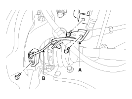
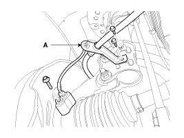
Remove the brake hose (A) & wheel speed sensor bracket (B) from
the front strut assembly by loosening mounting bolts.
|
| 3. |
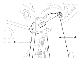
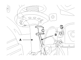
Disconnect the stabilizer link (B) with the front strut assembly
(A) after loosening the nut.
|
| 4. |
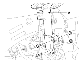
Disconnect the front strut assembly (A) with the knuckle by loosening
the bolt & nut.
|
| 5. |
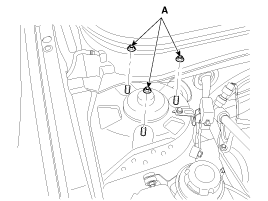
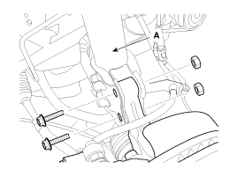
Remove the front strut assembly and then loosen the strut mounting
nuts (A).
|
| 6. |
Installation is the reverse of removal.
|
Disassembly
| 1. |
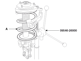
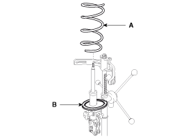
Compress the coil spring with a SST(09546-26000).
Do not compress the spring more than necessary.
|
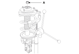
| 2. |
Loosen the self locking nuts (A).
|
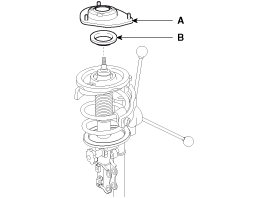
| 3. |
Remove the insulator assembly (A) and the strut bearing (B).
|
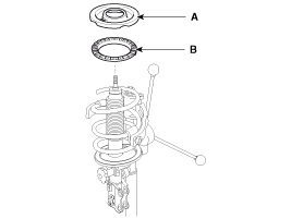
| 4. |
Remove the spring upper seat (A) and pad (B).
|
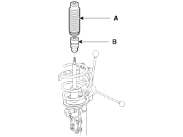
| 5. |
Remove the dust cover (A) and the bumper rubber (B).
|
| 6. |
Remove the coil spring (A) and the spring lower pad (B).
|
| 7. |
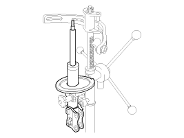
Remove the shock absorber (A) from the specialtool.
|
| 8. |
Reassembly is the reverse of the disassembly.
|
Inspection
| 1. |
Check the strut bearing for wear and damage.
|
| 2. |
Check the spring upper and lower seat for damage and deterioration.
|
| 3. |
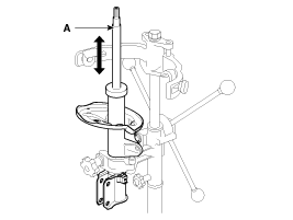
Compress and extend the piston rod (A) and check that there is
no abnormal resistance or unusual sound during operation.
|
 Front Strut Assembly. Components and Components Location
Components
1. Insulator cap
2. Insulator assembly
3. Strut bearing
4. Spring upper seat
5. Spring upper pad
6. Coil spring
7. Spring lower pad
8. Dust ...
 Front Lower Arm. Repair procedures - Revised
Replacement
1.
Remove the front wheel & tire.
Tightening torque:
88.3 ~ 107.9 N.m (9.0 ~ 11.0 kgf.m, 65.1 ~ 79.6 lb-ft)
...
See also:
AVN Head Unit. Repair procedures
Removal
AVN Head Unit
•
Take care not to scratch the center fascia panel and related
par ...
MENU : Audio CD
Press the CD MP3 mode key to set
the Repeat, Random, Information features.
Repeat
Press the key
► Set [
RPT] through the TUNE knob or
key to repeat the current song.
❈ Pres ...
Relay Box (Engine Compartment). Description and Operation
Description
Network Configuration
The Network of the SJB(Smart Junction Box) consists of Low speed CAN as
shown in the following figure.
Termination Resistor
The SJB has CAN ter ...

