 Hyundai Sonata: Brake Pedal. Repair procedures
Removal
| 1. |
Remove the crash pad lower panel. (Refer to the Body group- crash
pad).
|
| 2. |
Pull down steering column shaft after removing bolts and nuts.
(Refer to the steering group - Steering columm & shaft)
|
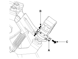
| 3. |
Disconnect the stop lamp switch connector (A).
|
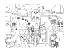
| 4. |
Remove the brake pedal member mounting nut (B).
|
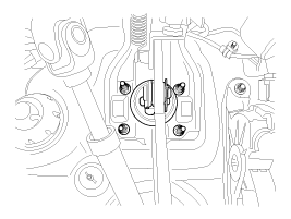
| 5. |
Remove the snap pin (A) and clevis pin (B).
|

| 6. |
Remove the brake pedal member assembly mounting nuts and then
remove the brake pedal assembly.
|
Inspection
| 1. |
Check the bushing for wear.
|
| 2. |
Check the brake pedal for bending or twisting.
|
| 3. |
Check the brake pedal return spring for damage.
|
| 4. |
Check the stop lamp switch.
|
Adjustment
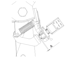
| Stop lamp switch clearance adjustment |
If the gap between stop lamp switch and bracket is not 1.0 ~ 2.0mm(0.04~
0.08in), conform to below.
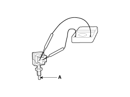
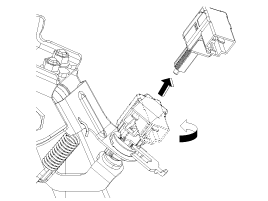
| 1. |
Disconnect the stop lamp switch connector (B).
|
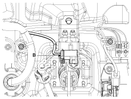
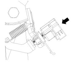
| 2. |
Release locking plate by pushing the hooks (B) carefully, and
then pull the locking plate (A) as indicated by the arrow (C).
|
| 3. |
Turn stop lamp switch 45° counterclockwise and remove it.
|
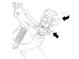
| 4. |
Fix the brake pedal arm and insert fully the stop lamp switch
as hiding contact part.
|
| 5. |
After inserting, turn the stop switch (A) 45° clockwise, and then
assemble locking plate (B) by pushing.
|
| 6. |
Confirm the gap between stop lamp switch and bracket.
|
| 7. |
Connect the stop lamp switch connector.
|
Installation
| 1. |
Installation is the reverse of removal.
|
| 2. |
Adjust the brake pedal height and free play.
|
| 3. |
Check the brake pedal operation.
|
 Brake Pedal. Components and Components Location
Components
1. Cowl bracket
2. Brake pedal member assembly
3. Stop lamp switch
4. Return spring
5. Brake pedal stopper
6. Clevis pin
7. Snap pin
8. Brak ...
 Front Disc Brake. Components and Components Location
Components
1. Guide rod bolt
2. Bleed screw
3. Caliper bracket
4. Caliper body
5. Inner pad shim
6. Brake pad
7. Pad retainer
...
See also:
Fuel Tank. Repair procedures
Removal
1.
Release the residual pressure in fuel line (Refer to “Release
Residual Pressure in Fuel Line” in this group).
2.
Remove the ...
Special Service Tools
Special Service Tools
Item
Illustration
Application
Fuel Pressure Gauge
(09353-24100)
Measuring the fuel line press ...
Disarmed stage
Using the smart key
The system will be disarmed when the doors are unlocked by pressing the unlock
button on the smart key or pressing the lock/unlock button of the front outside
door handle with ...
