 Hyundai Sonata: Engine Control Module (ECM). Schematic Diagrams
ECM Terminal And Input/Output signal
| ECM Terminal Function |
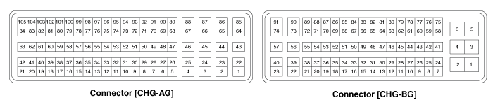
Connector [CHG-AG]
|
Pin No. |
Description |
Connected to |
|
1 |
Ignition Coil (Cylinder #2) control output |
Ignition Coil (Cylinder #2) |
|
2 |
- |
|
|
3 |
- |
|
|
4 |
- |
|
|
5 |
ETC Motor [+] control output |
ETC Motor |
|
6 |
ETC Motor [-] control output |
ETC Motor |
|
7 |
- |
|
|
8 |
- |
|
|
9 |
- |
|
|
10 |
- |
|
|
11 |
- |
|
|
12 |
Sensor power (+5V) |
Rail Pressure Sensor (RPS) |
|
A/C Pressure Transducer (APT) |
||
|
Power Steering Pressure Sensor (PSPS) |
||
|
Fuel Tank Pressure Sensor (FTPS) |
||
|
13 |
- |
|
|
14 |
Heated Oxygen Sensor (HO2S) [Bank 1/Sensor 2] signal input |
Heated Oxygen Sensor (HO2S) [Bank 1/Sensor 2] |
|
15 |
- |
|
|
16 |
- |
|
|
17 |
- |
|
|
18 |
- |
|
|
19 |
- |
|
|
20 |
Fuel Tank Pressure Sensor (FTPS) signal input |
Fuel Tank Pressure Sensor (FTPS) |
|
21 |
- |
|
|
22 |
Ignition Coil (Cylinder #4) control output |
Ignition Coil (Cylinder #4) |
|
23 |
- |
|
|
24 |
- |
|
|
25 |
- |
|
|
26 |
- |
|
|
27 |
- |
|
|
28 |
- |
|
|
29 |
- |
|
|
30 |
- |
|
|
31 |
- |
|
|
32 |
- |
|
|
33 |
Sensor power (+5V) |
Throttle Position Sensor (TPS) 1,2 |
|
34 |
- |
|
|
35 |
Sensor ground |
Heated Oxygen Sensor (HO2S) [Bank 1/Sensor 2] |
|
36 |
Ground |
Cruise Control Switch |
|
37 |
- |
|
|
38 |
- |
|
|
39 |
Rail Pressure Sensor (RPS) signal input |
Rail Pressure Sensor (RPS) |
|
40 |
- |
|
|
41 |
Sensor ground |
Fuel Tank Pressure Sensor (FTPS) |
|
42 |
- |
|
|
43 |
Shield |
Ignition Coil (Cylinder #1,2,3,4) |
|
44 |
- |
|
|
45 |
- |
|
|
46 |
- |
|
|
47 |
- |
|
|
48 |
- |
|
|
49 |
- |
|
|
50 |
- |
|
|
51 |
- |
|
|
52 |
- |
|
|
53 |
- |
|
|
54 |
Sensor ground |
Throttle Position Sensor (TPS) 1,2 |
|
55 |
Sensor ground |
Accelerator Position Sensor (APS) 2 |
|
56 |
Sensor ground |
Accelerator Position Sensor (APS) 1 |
|
57 |
Immobilizer communication line |
Smart Key Control Module [With Button Engine Start System] |
|
Immobilizer Control Module [Without Button Engine Start System] |
||
|
58 |
- |
|
|
59 |
Intake Air Temperature Sensor (IATS) signal input |
Intake Air Temperature Sensor (IATS) |
|
60 |
Sensor ground |
Rail Pressure Sensor (RPS) |
|
61 |
Sensor ground |
Manifold Absolute Pressure Sensor (MAPS) |
|
Intake Air Temperature Sensor (IATS) |
||
|
62 |
Sensor ground |
Engine Coolant Temperature Sensor (ECTS) |
|
63 |
Engine Coolant Temperature Sensor (ECTS) signal input |
Engine Coolant Temperature Sensor (ECTS) |
|
64 |
Ignition Coil (Cylinder #3) control output |
Ignition Coil (Cylinder #3) |
|
65 |
- |
|
|
66 |
- |
|
|
67 |
- |
|
|
68 |
- |
|
|
69 |
- |
|
|
70 |
- |
|
|
71 |
- |
|
|
72 |
- |
|
|
73 |
- |
|
|
74 |
- |
|
|
75 |
Throttle Position Sensor (TPS) 2 signal input |
Throttle Position Sensor (TPS) 2 |
|
76 |
Accelerator Position Sensor (APS) 2 signal input |
Accelerator Position Sensor (APS) 2 |
|
77 |
Accelerator Position Sensor (APS) 1 signal input |
Accelerator Position Sensor (APS) 1 |
|
78 |
- |
|
|
79 |
- |
|
|
80 |
Sensor ground |
A/C Pressure Transducer (APT) |
|
81 |
- |
|
|
82 |
Manifold Absolute Pressure Sensor (MAPS) signal input |
Manifold Absolute Pressure Sensor (MAPS) |
|
83 |
Rc/Rp (Pump Cell Voltage) |
Heated Oxygen Sensor [Bank 1/Sensor 1] |
|
84 |
VS-/IP- (Common Ground for VS, IP) |
Heated Oxygen Sensor [Bank 1/Sensor 1] |
|
85 |
Ignition Coil (Cylinder #1) control output |
Ignition Coil (Cylinder #1) |
|
86 |
- |
|
|
87 |
- |
|
|
88 |
- |
|
|
89 |
- |
|
|
90 |
- |
|
|
91 |
- |
|
|
92 |
- |
|
|
93 |
- |
|
|
94 |
- |
|
|
95 |
- |
|
|
96 |
Throttle Position Sensor (TPS) 1 signal input |
Throttle Position Sensor (TPS) 1 |
|
97 |
Sensor power (+5V) |
Accelerator Position Sensor (APS) 2 |
|
98 |
Sensor power (+5V) |
Accelerator Position Sensor (APS) 1 |
|
99 |
- |
|
|
100 |
- |
|
|
101 |
A/C Pressure Transducer (APT) signal input |
A/C Pressure Transducer (APT) |
|
102 |
- |
|
|
103 |
Sensor power (+5V) |
Manifold Absolute Pressure Sensor (MAPS) |
|
104 |
Rc (Compensative Resistance) |
Heated Oxygen Sensor [Bank 1/Sensor 1] |
|
105 |
VS+ (NERNST Cell Voltage) |
Heated Oxygen Sensor [Bank 1/Sensor 1] |
Connector [CHG-BG]
|
Pin No. |
Description |
Connected to |
|
1 |
ECM ground |
Chassis ground |
|
2 |
ECM ground |
Chassis ground |
|
3 |
Battery power (B+) |
Main Relay |
|
4 |
ECM ground |
Chassis ground |
|
5 |
Battery power (B+) |
Main Relay |
|
6 |
Battery power (B+) |
Main Relay |
|
7 |
- |
|
|
8 |
Crankshaft Position Sensor (CKPS) signal input |
Crankshaft Position Sensor (CKPS) |
|
9 |
- |
|
|
10 |
Brake Switch 2 signal input |
Brake Switch |
|
11 |
- |
|
|
12 |
- |
|
|
13 |
- |
|
|
14 |
- |
|
|
15 |
Electrical load signal input |
Alternator |
|
16 |
Alternator PWM signal output |
Alternator |
|
17 |
- |
|
|
18 |
Cooling Fan Relay [High] control output |
Cooling Fan Relay [High] |
|
19 |
Immobilizer Lamp control output |
Immobilizer Lamp [Without Button Engine Start System] |
|
20 |
- |
|
|
21 |
- |
|
|
22 |
Injector (Cylinder #2) [High] control output |
Injector (Cylinder #2) |
|
23 |
Injector (Cylinder #2) [Low] control output |
Injector (Cylinder #2) |
|
24 |
- |
|
|
25 |
Sensor ground |
Crankshaft Position Sensor (CKPS) |
|
26 |
- |
|
|
27 |
Brake Switch 1 signal input |
Brake Switch |
|
28 |
- |
|
|
29 |
Camshaft Position Sensor (CMPS) [Bank 1/Intake] signal input |
Camshaft Position Sensor (CMPS) [Bank 1/Intake] |
|
30 |
Camshaft Position Sensor (CMPS) [Bank 1/Exhaust] signal input |
Camshaft Position Sensor (CMPS) [Bank 1/Exhaust] |
|
31 |
- |
|
|
32 |
LIN communication signal input |
Battery Sensor |
|
33 |
Cooling Fan Relay [Low] control output |
Cooling Fan Relay [Low] |
|
34 |
- |
|
|
35 |
- |
|
|
36 |
- |
|
|
37 |
Malfunction Indicator Lamp (MIL) control output |
Malfunction Indicator Lamp (MIL) |
|
38 |
- |
|
|
39 |
Injector (Cylinder #3) [High] control output |
Injector (Cylinder #3) |
|
40 |
 Components and Components Location
Components Location
1. Engine Control Module (ECM)
2. Manifold Absolute Pressure Sensor (MAPS)
3. Intake Air Temperature Sensor (IATS)
4. Engine Coolant Temperature Sensor ...
 Engine Control Module (ECM). Repair procedures
Removal
When replacing the ECM, the vehicle equipped with the immobilizer
must be performed procedure as below.
...
See also:
Input Speed Sensor. Repair procedures
Removal
1.
Remove the battery and the battery tray. (Refer to
"Charging system" in EE group.)
2.
Remove the under cover (A).
...
Sunglass holder
To open the sunglass holder, press the cover and the holder will slowly open.
Place your sunglasses in the compartment door with the lenses facing out. Push to
close.
WARNING
Do not keep ...
Body Control Module (BCM). Specifications
Specifications
Items
Specifications
Rated voltage
DC 12V
Operating voltage
DC 9 ~ 16V
Operating temp ...
