Inspection
|
1. |
Connect the GDS on the Data Link Connector (DLC).
|
|
2. |
Measure the output voltage of the MAPS at idle and IG ON.
Specification:
Refer to "Specification"
|
|
Removal
|
1. |
Turn the ignition switch OFF and disconnect the battery negative
(-) cable.
|
|
2. |
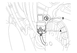
Disconnect the manifold absolute pressure sensor connector (A).
|
|
3. |
Remove the installation bolt (B), and then remove the sensor from
the surge tank.
|
Installation
| •
|
Install the component with the specified torques.
|
| •
|
Note that internal damage may occur when the component
is dropped. If the component has been dropped, inspect before
installing.
|
|
| •
|
Insert the sensor in the installation hole and be careful
not to damage.
|
|
|
1. |
Installation is reverse of removal.
Manifold absolute pressure sensor
installation bolt:
9.8 ~ 11.8 N.m (1.0 ~ 1.2 kgf.m, 7.2 ~ 8.7 lb-ft)
|
|
Description
Intake Air Temperature Sensor (IATS) is included inside Manifold Absolute
Pressure Sensor and detects the intake air temperature.
To calculate precise air quantity, correction o ...

 Hyundai Sonata: Manifold Absolute Pressure Sensor (MAPS). Repair procedures
 Manifold Absolute Pressure Sensor (MAPS). Schematic Diagrams
 Intake Air Temperature Sensor (IATS). Description and Operation