 Hyundai Sonata: Relay Box (Engine Compartment). Repair procedures
Inspection
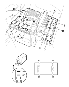
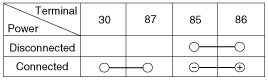
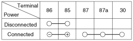
Power Relay Test (Type A)
|
Check for continuity between the terminals.
|
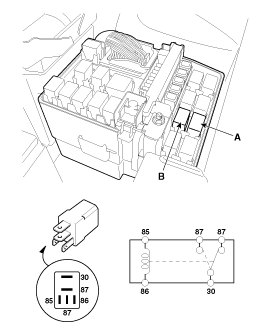
A. Front deicer B. Back up lamp relay C. IGN2 D. Start #1 relay (H1) E. HAC relay F. IGN1 G. Start #2 relay |
H. Cooling fan (HI) relay I. Cooling fan (LO) relay J. Blower relay K. Rear defogger L. Horn relay M. ACC N. Fuel pump relay |
| 1. |
There should be continuity between the No.30 and No.87 terminals
when power and ground are connected to the No.85 and No.86 terminals.
|
| 2. |
There should be no continuity between the No.30 and No.87 terminals
when power is disconnected.
|
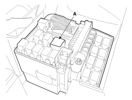
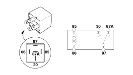
Power Relay Test (Type C)
Check for continuity between the terminals.
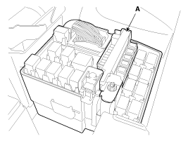
A : Main relay
| 1. |
There should be continuity between the No.30, 87a and No.87 terminals
when power and ground are connected to the No.85 and No.86 terminals.
|
| 2. |
There should be no continuity between the No.30, 87a and No.87
terminals when power is disconnected.
|
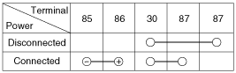
Power Relay Test (Type B)
Check for continuity between the terminals.
A : Rain sensor relay
B : Wiper relay
| 1. |
There should be continuity between the No.30 and No.87 terminals
when power and ground are connected to the No.85 and No.86 terminals.
|
| 2. |
There should be continuity between the No.30 and No.87 terminals
when power is disconnected.
|
Fuse Inspection
| 1. |
Be sure there is no play in the fuse holders, and that the fuses
are held securely.
|
| 2. |
Are the fuse capacities for each circuit correct?
|
| 3. |
Are there any blown fuses?
If a fuse is to be replaced, be sure to use a new fuse of the
same capacity. Always determine why the fuse blew first and completely
eliminate the problem before installing a new fuse.
|
Multi Fuse
Multi Fuse is for optimizing the engine room package.
|
 Relay Box (Engine Compartment). Description and Operation
Description
Network Configuration
The Network of the SJB(Smart Junction Box) consists of Low speed CAN as
shown in the following figure.
Termination Resistor
The SJB has CAN ter ...

See also:
Cowl Top Cover. Repair procedures
Replacement
1.
Remove the covers and remove the nuts, then remove the wiper arm
(A).
2.
Detach the clips, then remove the cowl top ...
Shift Lever. Components and Components Location
Components
1. Shift lever knob
2. Shift lever assembly
3. Sport mode connector
4. Control cable assembly
5. Retainer
6. Automatic transaxle assembly
...
Anti-lock brake system (ABS)
WARNING
ABS (or ESC) will not prevent accidents due to improper or dangerous driving
maneuvers. Even though vehicle control is improved during emergency braking, always
maintain a safe distance b ...
