 Hyundai Sonata: Repair procedures
Inspection
Lighting Switch Inspection
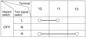
With the multifunction switch in each position, make sure that continuity
exists between the terminals below. If continuity is not as specified, replace
the multi-function switch.
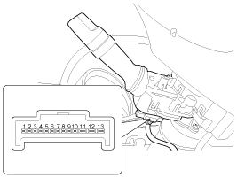
Lighting Switch (Auto Light)
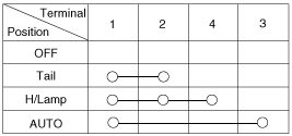
Lighting Switch
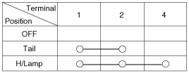
Dimmer And Passing Switch
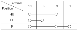
HU : Head lamp high beam
HL : Head lamp low beam
P : Head lamp passing switch
Turn Signal Switch
Front Fog Lamp Switch

Hazard Switch

※ FL : Flash unit
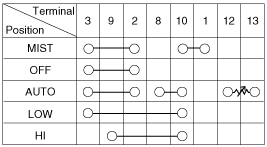
Wiper And Washer Switch Inspection
With the multifunction switch in each position, make sure that continuity
exists between the terminals below. If continuity is not as specified, replace
the multi-function switch.
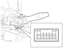
Wiper Switch
Washer Switch

Inspection (With GDS)
| 1. |
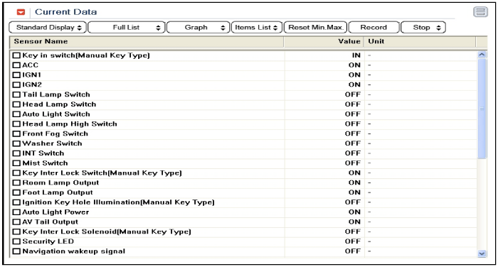
Check BCM input/output specification of multifunction switch using
the GDS. If the specification is abnormal, replace the lamp or wiper
switch.
|
| 2. |
If diagnosis is required on the multifunction switch, select model
and "BCM".
|
| 3. |
To consult the present input/output value of BCM, "Current DATA".
It provides information of BCM input/output conditions of power supply,
turn signal/brake lamp, headlamp, door, locks, outside mirror, wiper,
auto-light and transmitters etc.
|
| 4. |
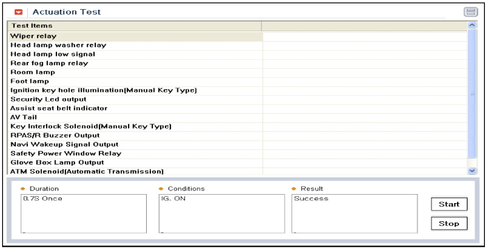
To perform compulsory operation on BCM input factors, select "ACTUATION
TEST".
|
Removal
| 1. |
Disconnect the negative (-) battery terminal.
|
| 2. |
Remove the steering wheel.
(Refer to the ST group - "Steering column & shaft")
|
| 3. |
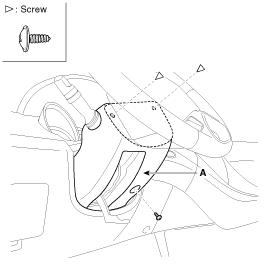
Remove the steering column upper and lower shrouds after removing
3 screws.
|
| 4. |
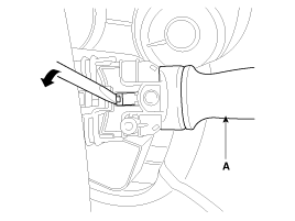
If it is necessary to remove. The wiper & washer switch (A) only,
release the lock of wiper switch using tool without removing the steering
wheel and the clock spring.
|
| 5. |
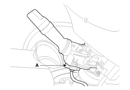
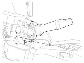
Disconnect the lighting switch connector (A) and wiper & washer
switch connector (B).
|
| 6. |
Remove the steering wheel.
(Refer to the ST group - "Steering column & shaft")
|
| 7. |
Remove the clock spring.
(Refer to the RT group - "Airbag module")
|
| 8. |
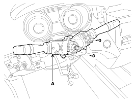
Remove the multifunction switch assembly (A) after loosening the
mounting screws.
|
Installation
| 1. |
Install the multifunction switch.
|
| 2. |
Install the clock spring.
|
| 3. |
Install the steering column upper and lower shrouds.
|
| 4. |
Install the steering wheel.
|
 Components and Components Location
Component
...
 Horn
Horn
...
See also:
Identification Number Locations
...
Side Airbag (SAB) Module. Repair procedures
Removal
The side airbag cannot be disassembled from the seat back assembly,
so replace the seat back assembly when replacing ...
Panoramaroof. Repair procedures
Replacements
Glass Replacement
1.
Remove the cover (A).
2.
After loosening the mounting screws, then remove the movable glass
...

