Hyundai Sonata: Shift Lever. Repair procedures - Manual Transaxle Control System - Manual Transaxle SystemHyundai Sonata: Shift Lever. Repair procedures

Removal

1.
Remove the front console assembly.(Refer to "Interior" in BD group)
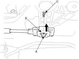
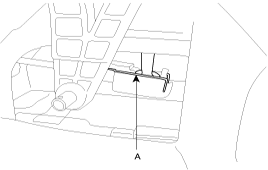
2.
Remove the snap pin (A) and the clips (B).
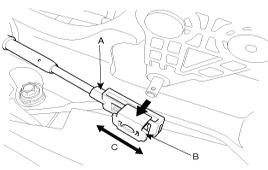
3.
Remove the clip(A) from the shift cable.
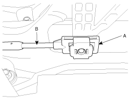
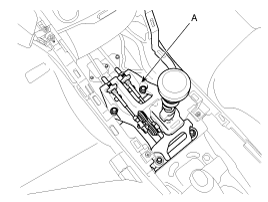
4.
Remove the shift lever assembly (A).
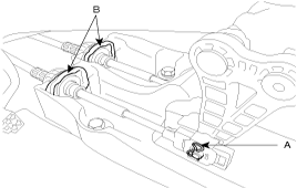
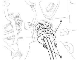
Tightening torque :
8.8~13.7N.m (0.9~1.4kgf.m, 6.5~10.1Ib-ft)

5.
Remove the retainer (A) and the nuts (B).

Tightening torque :
9.8~14.7N.m (1.0~1.5kgf.m, 7.2~10.8Ib-ft)

6.
Remove the cable from the bracket at tranmission side (Refer to "Transaxle" in this group).
7.
Remove the select cable and shift cable.

Inspection

1.
Check the select cable for proper operation and for damage.
2.
Check the shift cable for proper operation and for damage.
3.
Check the boots for damage.
4.
Check the boots for wear abrasion sticking, restricted movement or damage.
5.
Check for the weak or damaged spring.

Installation

1.
Installation is the reverse of removal.
•
Move the slide clip (B) of guide member (A) in the direction as shown in the illustration.
Adjust the slide clip fit into the select lever moving the slide clip in the direction(C).

•
Install the guide member (A) of the select cable (B).

•
Adjust the slide clip (B) to fit it into the select lever pin (A) and install the snap pin (C).
Insert the slide clip in the direction as shown in the illustration.


    Shift Lever. Components and Components Location
    Components 1. Shift lever assembly 2. Gear shift cable assembly 3. Clips 4. Retainer ...

    See also:

    Operation in foreign countries
    If you are going to drive your vehicle in another country, be sure to: Observe all regulations regarding registration and insurance. Determine that acceptable fuel is available. ...

    Shift Lever. Components and Components Location
    Components 1. Shift lever knob 2. Shift lever assembly 3. Sport mode connector 4. Control cable assembly 5. Retainer 6. Automatic transaxle assembly ...

    Manifold Absolute Pressure Sensor (MAPS). Repair procedures
    Inspection 1. Connect the GDS on the Data Link Connector (DLC). 2. Measure the output voltage of the MAPS at idle and IG ON. ...