 Hyundai Sonata: TPMS Receiver. Schematic Diagrams
Circuit Diagram
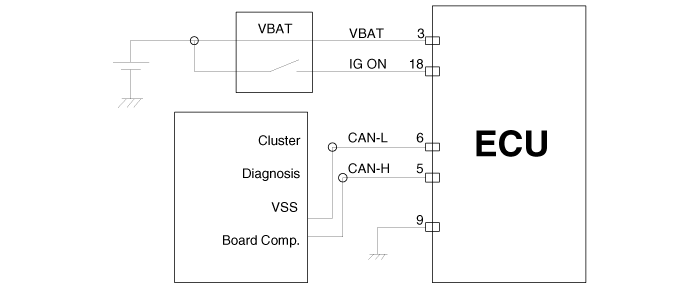
| Connector pin number |

|
Pin NO. |
Discription |
Remark |
|
1 |
- |
|
|
2 |
- |
|
|
3 |
ECU battery terminal |
|
|
4 |
- |
|
|
5 |
CAN_High |
|
|
6 |
CAN_Low |
|
|
7 |
- |
|
|
8 |
- |
|
|
9 |
Ground |
|
|
10 |
- |
|
|
11 |
- |
|
|
12 |
- |
|
|
13 |
- |
|
|
14 |
- |
|
|
15 |
- |
|
|
16 |
- |
|
|
17 |
- |
|
|
18 |
Ignition ON |
|
|
19 |
- |
|
|
20 |
- |
|
 TPMS Receiver. Description and Operation
Description
1.
Mode
(1)
Virgin State
A.
The receiver as a sole part is shipped in this
...
 TPMS Receiver. Description and Operation
Operation
1.
General Function
A.
Auto-locate/learn takes place only once per Ignition cycle.
B.
O ...
See also:
Body Control Module (BCM). Components and Components Location
Components
...
Components and Components Location
Components
1. Receiver
2. TPMS sensor (FL)
3. TPMS sensor (RL)
4. TPMS sensor (RR)
5. TPMS sensor (FR)
...
Smart key unit. Schematic Diagrams
Circuit Diagram
...
