
 Hyundai Sonata: Trip Switch. Repair procedures
Inspection
| 1. |
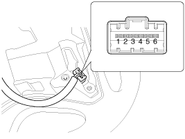
Check the audio remote control switch for resistance between No.3
and No.5 terminals in each switch position.
|
| 2. |
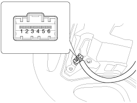
In case of RH, check the audio remote control switch for resistance
between No.3 and No.4 (No.4 and No.6) terminals in each switch position.
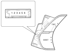
[Trip + Mute]
[Trip Switch]
|
Removal
| 1. |
Disconnect the negative (-) battery terminal.
|
| 2. |
Remove the driver airbag module.
(Refer to the RT group)
|
| 3. |
Remove the steering wheel.
(Refer to the ST group - "Steering column & shaft")
|
| 4. |
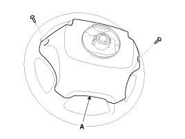
Remove the steering wheel cover (A) after loosening the screws.
|
| 5. |
Remove the steering wheel remote control switch connector (A)
after loosening the mounting screws.
|
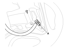
Installation
| 1. |
Reassemble the steering wheel remote control switch after connecting
the connector.
|
| 2. |
Reassemble the steering wheel.
|
| 3. |
Reassemble the driver airbag module.
|

 Trip Switch. Schematic Diagrams
Circuit Diagram
...
 Troubleshooting
Troubleshooting
Symptom
Possible cause
Remedy
Speedometer does not operate
Fuse (MODULE1 7.5A and Room lamp 10A) in smart junction box ...
See also:
Limitation of Active ECO operation
If the following conditions occur while Active ECO is operating, the system operation
is limited even though there is no change in the ECO indicator.
When the coolant temperature is low: The sys ...
Interior Trim. Components and Components Location
Components
1. Front pillar trim
2. Center pillar upper trim
3. Center pillar lower trim
4. Rear pillar trim
5. Cowl side trim
6. Front door scuff trim
7. ...
Automatic Transaxle. Repair procedures
Removal
1.
Remove the following items;
A.
Air duct (A) and engine cover (B). (Refer
to "Intake and Exhaust system" in EM group. ...
