 Hyundai Sonata: Input Speed Sensor. Repair procedures
Removal
| 1. |
Remove the battery and the battery tray. (Refer to
"Charging system" in EE group.)
|
| 2. |
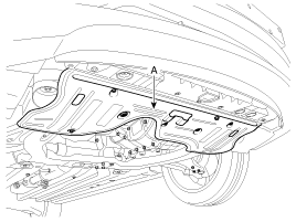
Remove the under cover (A).
|
| 3. |
Replace new gasket and the plug after drining the
automatic transaxle fluid by removing the drain plug.
(Refer to "Automatic transaxle system" in this group.)
|
| 4. |
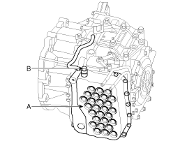
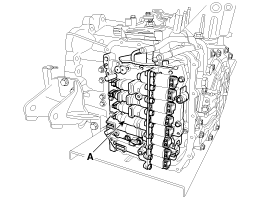
Remove the valve body cover (A) and eyebolt (B).
|
| 5. |
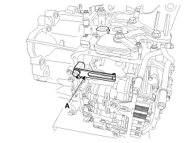
Remove the plate and the detend spring (A) after
removing the bolt.
|
| 6. |
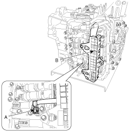
Remove the bolt (3ea) after disconnecting the solenoid
valve connector (A) and the oil temperature sensor connector (B).
|
| 7. |
Remove the valve body assembly (A).
|
| 8. |
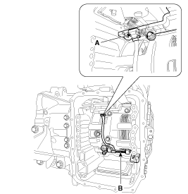
Disconnect the input & output speed sensor connector(A).
|
| 9. |
Remove the input & output speed sensor (B) after
removing the bolts(2ea).
|
Installation
| 1. |
Installation is the reverse of removal.
|
After replacement or reinstallation procedure of
the valve body assembly, must perform procedures below.
|
 Input Speed Sensor. Specifications
Specification
Item
Specification
Type
Hall Effect Sensor, 2pins (Power: 9V, Signal)
Operation condition
-40 ~15 ...
 Output Speed Sensor. Description and Operation
Description
- Integrated one unit for input & output speed sensor
- Differential current type (low: 7mA, high: 14mA)
- Failsafe: 4th gear hold (D), 2nd ~ 4th manual shift (S)
...
See also:
Engine compartment fuse replacement
1. Turn the ignition switch and all other switches off.
2. Remove the fuse panel cover by pressing the tab and pulling up.
3. Check the removed fuse; replace it if it is blown. To remove or inse ...
Theft-alarm system
This system is designed to provide protection from unauthorized entry into the
vehicle. This system is operated in three stages: the first is the "Armed" stage,
the second is the " ...
Steering wheel audio control
The steering wheel may incorporate audio control buttons.
CAUTION
Do not operate audio remote control buttons simultaneously.
1. VOLUME (VOL+/-)
Push the lever upward (+) to increase the volu ...

