 Hyundai Sonata: Solenoid valve. Repair procedures
Removal
| 1. |
Remove the battery and the battery tray. (Refer to
"Charging system" in EE group.)
|
| 2. |
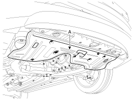
Remove the under cover (A).
|
| 3. |
Replace new gasket and the plug after drining the
automatic transaxle fluid by removing the drain plug.
(Refer to "Automatic transaxle system" in this group.)
|
| 4. |
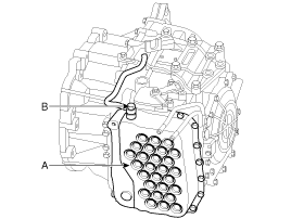
Remove the valve body cover (A) and eyebolt (B).
|
| 5. |
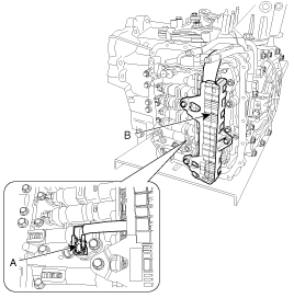
Remove the bolt (3ea) after disconnecting the solenoid
valve connector (B) and the oil temperature sensor connector (A).
|
| 6. |
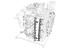
Remove the solenoid valve (A) after removing the
solenoid support.
|
Installation
| 1. |
Installation is the reverse of removal.
|
After replacement or reinstallation procedure of
the valve body assembly, must perform procedures below.
|
 Solenoid valve. Specifications
Specification
Item
Function
Piece
Specification
VFS
26/B
T/Con
2
Control p ...
See also:
Interior light
CAUTION
Do not use the interior lights for extended periods when the engine is not
running. It may cause battery discharge.
WARNING
Do not use the interior lights when driving in the dark. Accide ...
Vehicle identification number (VIN)
2.4 engine
2.0 engine
The vehicle identification number (VIN) is the number used in registering your
car and in all legal matters pertaining to its ownership, etc.
The number is punched o ...
BASIC METHOD OF USE : Audio CD / MP3 CD / USB / iPod / My Music
Press the key to change the mod
mode in order of CD➟USB(iPod)➟AUX ➟My Music➟BT Audio.
The folder/file name is displayed on the screen.
❈ The CD is automatical ...


