
 Hyundai Sonata: Components and Components Location
Components Location
|
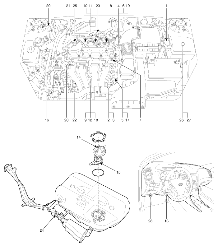
1. Engine Control Module (ECM) 2. Manifold Absolute Pressure Sensor (MAPS) 3. Intake Air Temperature Sensor (IATS) 4. Engine Coolant Temperature Sensor (ECTS) 5. Throttle Position Sensor (TPS) [integrated into ETC Module] 6. Crankshaft Position Sensor (CKPS) 7. Camshaft Position Sensor (CMPS) [Bank 1 / Intake] 8. Camshaft Position Sensor (CMPS) [Bank 1 / Exhaust] 9. Knock Sensor (KS) 10. Heated Oxygen Sensor (HO2S) [Bank 1 / Sensor 1] 11. Heated Oxygen Sensor (HO2S) [Bank 1 / Sensor 2] 12. Rail Pressure Sensor (RPS) 13. Accelerator Position Sensor (APS) 14. Fuel Tank Pressure Sensor (FTPS) 15. Fuel Level Sensor (FLS) |
16. A/C Pressure Transducer (APT) 17. ETC Motor [integrated into ETC Module] 18. Injector 19. Purge Control Solenoid Valve (PCSV) 20. CVVT Oil Control Valve (OCV) [Bank 1 / Intake] 21. CVVT Oil Control Valve (OCV) [Bank 1 / Exhaust] 22. Variable Intake Solenoid (VIS) Valve 23. Fuel Pressure Regulator Valve 24. Canister Close Valve (CCV) 25. Ignition Coil 26. Main Relay 27. Fuel Pump Relay 28. Data Link Connector (DLC) [16-Pin] 29. Multi-Purpose Check Connector [20-Pin] |
|
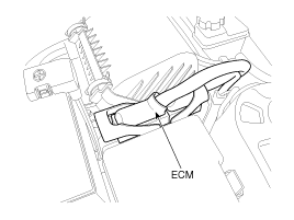
1. Engine Control Module (ECM) |
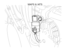
2. Manifold Absolute Pressure Sensor (MAPS) 3. Intake Air Temperature Sensor (IATS) |
|
|
|
|
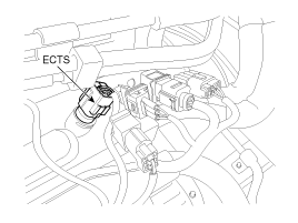
4. Engine Coolant Temperature Sensor (ECTS) |
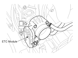
5. Throttle Position Sensor (TPS) 16. ETC Motor |
|
|
|
|
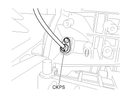
6. Crankshaft Position Sensor (CKPS) |
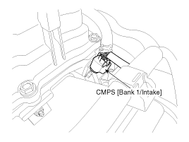
7. Camshaft Position Sensor (CMPS) [Bank 1 / Intake] |
|
|
|
|
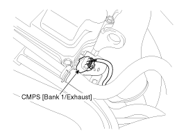
8. Camshaft Position Sensor (CMPS) [Bank 1 / Exhaust] |
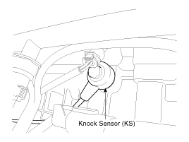
9. Knock Sensor (KS) |
|
|
|
|
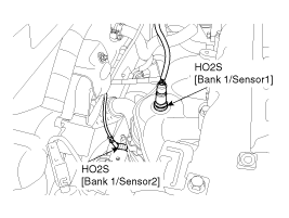
10. Heated Oxygen Sensor (HO2S) [Bank 1/Sensor 1] [SULEV] 11. Heated Oxygen Sensor (HO2S) [Bank 1/Sensor 2] [SULEV] |
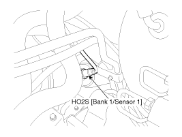
10. Heated Oxygen Sensor (HO2S) [Bank 1/Sensor 1] [ULEV] |
|
|
|
|
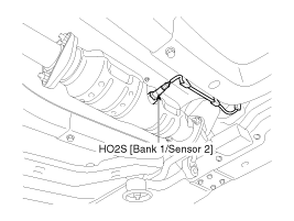
11. Heated Oxygen Sensor (HO2S) [Bank 1/Sensor 2] [ULEV] |
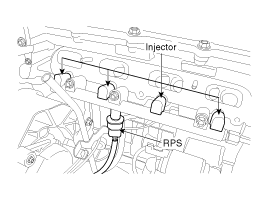
12. Rail Pressure Sensor (RPS) 18. Injector |
|
|
|
|
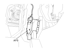
13. Accelerator Position Sensor (APS) |
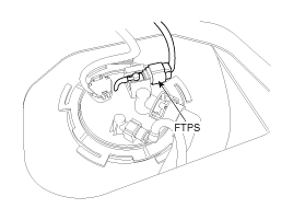
14. Fuel Tank Pressure Sensor (FTPS) |
|
|
|
|
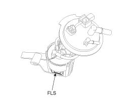
15. Fuel Level Sensor (FLS) |
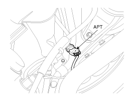
16. A/C Pressure Transducer (APT) |
|
|
|
|
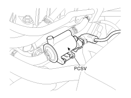
19. Purge Control Solenoid Valve (PCSV) |
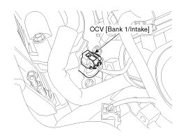
20. CVVT Oil Control Valve (OCV) [Bank 1 / Intake] |
|
|
|
|
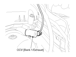
21. CVVT Oil Control Valve (OCV) [Bank 1 / Exhaust] |
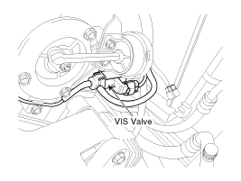
22. Variable Intake Solenoid (VIS) Valve |
|
|
|
|
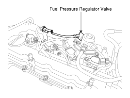
23. Fuel Pressure Regulator Valve |
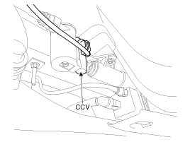
24. Canister Close Valve (CCV) |
|
|
|
|
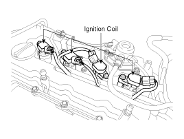
25. Ignition Coil |
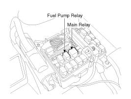
26. Main Relay 27. Fuel Pump Relay |
|
|
|
|
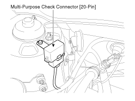
28. Multi-Purpose Check Connector [20-Pin] |
|
|
|
 Description and Operation
OBD-II review
1. Overview
The California Air Resources Board (CARB) began regulation of On Board
Diagnostics (OBD) for vehicles sold in California beginning with the 1988 model
year. The ...
 Engine Control Module (ECM). Schematic Diagrams
ECM Terminal And Input/Output signal
ECM Terminal Function
Connector [CHG-AG]
Pin
No.
Description
Connected to
1
I ...
See also:
Hazardous driving conditions
When hazardous driving conditions are encountered such as water, snow, ice, mud,
sand, or similar hazards, follow these suggestions:
Drive cautiously and allow extra distance for braking.
...
Air bag warning label (if equipped)
Air bag warning labels, some required by the U.S. National Highway Traffic Safety
Administration (NHTSA), are attached to alert the driver and passengers of potential
risks of the ...
Rear Upper Arm. Repair procedures
Removal
1.
Remove the rear wheel & tire.
Tightening torque:
88.3 ~ 107.9 N.m (9.0 ~ 11.0 kgf.m, 65.1 ~ 79.6 lb-ft)
...
