
 Hyundai Sonata: Power Door Lock Actuators. Repair procedures
Inspection
| 1. |
Remove the front door trim.
(Refer to the BD group - "Front door")
|
| 2. |
Remove the front door module.
|
| 3. |
Disconnect the 7P connector from the actuator.
В�е подробно�ти урна дл� батареек на нашем �айте.
|
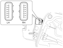
| 4. |
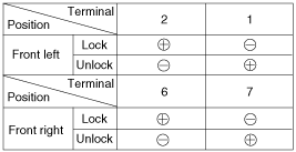
Check actuator operation by connecting power and ground according
to the table. To prevent damage to the actuator, apply battery voltage
only momentarily.
|
| 1. |
Remove the rear door trim.
(Refer to the BD group - "Rear door")
|
| 2. |
Remove the rear door module.
|
| 3. |
Disconnect the 7P connector from the actuator.
|
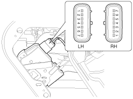
| 4. |
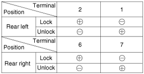
Check actuator operation by connecting power and ground according
to the table. To prevent damage to the actuator, apply battery voltage
only momentarily.
|
| 1. |
Remove the trunk lid trim panel.
(Refer to the BD group - "Trunk lid")
|
| 2. |
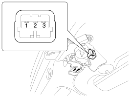
Disconnect the 3P connector from the actuator.
|
| 3. |
Check actuator operation by connecting power and ground according
to the table. To prevent damage to the actuator, apply battery voltage
only momentarily.
|

| 1. |
Remove the front door trim panel.
(Refer to the BD group - "Front door")
|
| 2. |
Remove the front door module.
|
| 3. |
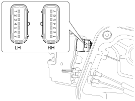
Disconnect the 7P connector from the actuator.
|
| 4. |
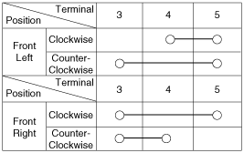
Check for continuity between the terminals in each switch position
when inserting the key into the door according to the table.
|
| 1. |
Remove the rear door trim panel.
(Refer to the BD group - "Rear door")
|
| 2. |
Remove the rear door module.
|
| 3. |
Disconnect the 7P connector from the actuator.
|
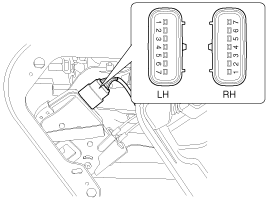
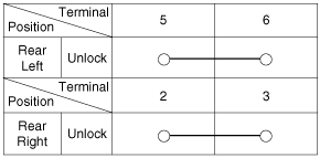
| 4. |
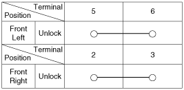
Check for continuity between the terminals in each switch position
according to the table.
|
| 1. |
Remove the trunk lid trim.
(Refer to the BD group - "Trunk lid")
|
| 2. |
Disconnect the 3P connector from the actuator.
|
| 3. |
Check for continuity between the terminals in each switch position
according to the table.
|

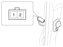
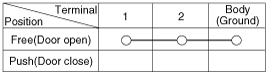
| 1. |
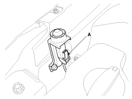
Disconnect the connector from the hood switch (A).
|
| 2. |
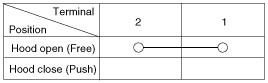
Check for continuity between the terminals and ground according
to the table.
|
| 1. |
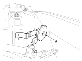
Remove the burglar horn (A) after removing 1 bolt and disconnect
the 2P connector from the burglar horn.
|
| 2. |
Test the burglar horn by connecting battery power to the terminal
1 and ground the terminal 2.
|
| 3. |
The burglar horn should make a sound. If the burglar horn fails
to make a sound replace it.
|
 Components and Components Location
Component Location
1. Driver power window switch
2. Door lock switch
3. BCM (Body Control Module)
4. Front door lock actuator
5. Rear door lock actuator
6. T ...
 Power Door Lock Relay. Repair procedures
Inspection
1.
Disconnect the negative (-) battery terminal.
2.
Remove the junction box.
3.
Check for continuit ...
See also:
Turn signals and lane change signals
The ignition switch must be on for the turn signals to function. To turn on the
turn signals, move the lever up or down (A). Green arrow indicators on the instrument
panel indicate which turn ...
Smart key unit. Components and Components Location
Component (1)
Connector Pin Information
Pin
Connector A
Pin
Connector B
1
Battery
1
Interior 2 an ...
Opening the fuel filler lid
The fuel filler lid must be opened from inside the vehicle by pushing the fuel
filler lid opener button.
✽ NOTICE
If the fuel filler lid will not open because ice has formed around it, ...
