 Hyundai Sonata: Front Disc Brake. Repair procedures
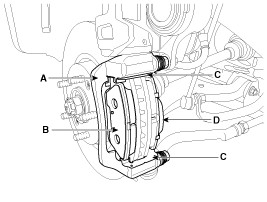
Removal
| 1. |
Remove the front wheel & tire.
|
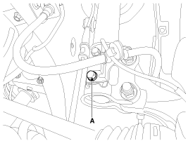
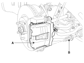
| 2. |
Loosen the hose eyebolt (B) and caliper mounting bolts (C), then
remove the front caliper assembly (A).
|
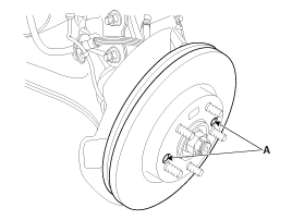
| 3. |
Remove the front brake disc by loosening the screws (A).
|
Replacement
Front brake pads
| 1. |
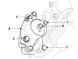
Remove the brake hose mounting bracket bolt (A).
|
| 2. |
Loosen the guide rod bolt (B) and pivot the caliper (A) up out
of the way.
|
| 3. |
Replace pad shim (D), pad retainers (C) and brake pads (B) in
the caliper bracket (A).
|
Inspection
Front brake disc thickness check
| 1. |
Check the brake pads for wear and fade.
|
| 2. |
Check the brake disc for damage and cracks.
|
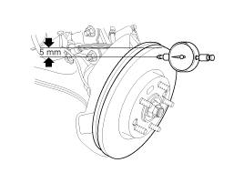
| 3. |
Remove all rust and contamination from the surface, and measure
the disc thickness at 8 points, at least, of same distance (5mm) from
the brake disc outer circle.
|
| 4. |
If wear exceeds the limit, replace the discs and pad assembly
left and right of the vehicle.
|
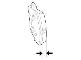
Front Brake Pad Check
| 1. |
Check the pad wear. Measure the pad thickness and replace it,
if it is less than the specified value.
|
| 2. |
Check that grease is applied, to sliding contact points and the
pad and backing metal for damage.
|
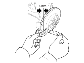
Front brake disc runout check
| 1. |
Place a dial gauge about 5mm (0.2 in.) from the outer circumference
of the brake disc, and measure the runout of the disc.
|
| 2. |
If the runout of the brake disc exceeds the limit specification,
replace the disc, and then measure the runout again.
|
| 3. |
If the runout does not exceed the limit specification, install
the brake disc after turning it 180° and then check the runout of the
brake disc again.
|
| 4. |
If the runout cannot be corrected by changing the position of
the brake disc, replace the brake disc.
|
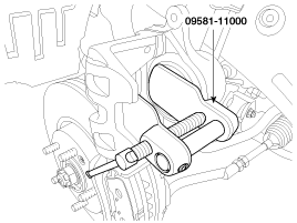
Installation
| 1. |
Installation is the reverse of removal.
|
| 2. |
Use a SST (09581-11000) when installing the brake caliper assembly.
|
| 3. |
After installation, bleed the (Refer to Brake system bleeding)
|
|
 Front Disc Brake. Components and Components Location
Components
1. Guide rod bolt
2. Bleed screw
3. Caliper bracket
4. Caliper body
5. Inner pad shim
6. Brake pad
7. Pad retainer
...
 Rear Disc Brake. Components and Components Location
Components
1. Guide rod bolt
2. Bleed screw
3. Caliper bracket
4. Caliper body
5. Inner pad shim
6. Brake pad
7. Pad retainer
...
See also:
Head Lamps. Components and Components Location
Component
1. Head lamp assembly lens & housing
2. Head lamp (High) lamp
3. Dust cap
4. Socket
5. Turn signal/ Position lamp
6. Head lamp (Low) lamp
...
Valve Body. Repair procedures
Removal
1.
Remove the battery and the battery tray. (Refer to
"Charging system" in EE group.)
2.
Remove the under cover (A).
...
Road warning
Hazard warning flasher
The hazard warning flasher serves as a warning to other drivers to exercise extreme
caution when approaching, overtaking, or passing your vehicle.
It should be used when ...
