 Hyundai Sonata: Front Driveshaft. Repair procedures - Revised
Replacement
| 1. |
Loosen the wheel nuts slightly.
Raise the vehicle, and make sure it is securely supported.
|
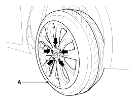
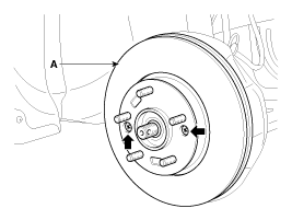
| 2. |
Remove the front wheel and tire (A) from front hub .
|
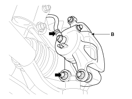
| 3. |
Remove the brake caliper mounting bolts , and then place the brake
caliper assembly (B) with wire.
|
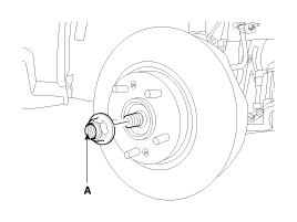
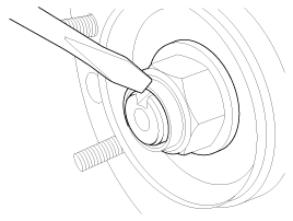
| 4. |
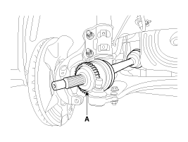
Remove driveshaft nut (A) from the front hub under applying the
break.
|
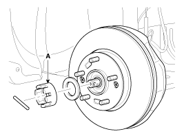
| 5. |
Loosen the front brake disc mount screw and then remove the front
brake disc (A).
|
| 6. |
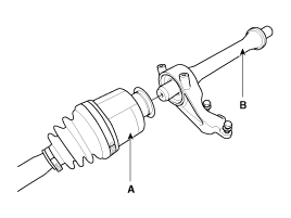
Remove the tie rod end ball joint (A) from the knuckle.
|
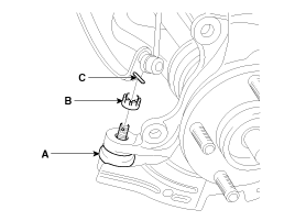
| 7. |
Loosen the mount bolt and then remove the wheel speed sensor (A)
from knuckle.
|
| 8. |
Remove the lower arm (A) from the knuckle.
|
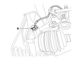
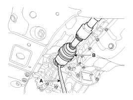
| 9. |
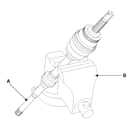
Disconnect the driveshaft (A) from the front hub assembly.
|
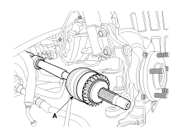
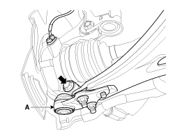
| 10. |
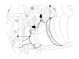
Insert a pry bar (A) between the transaxle case and joint case,
and separate the drive shaft (B) from the transaxle case.
|
| 11. |
Install in the reverse order of removal.
|
| 12. |
Check the alignment. (Refer to SSgroup 'Tires/Wheels - alingment')
|
Replacement
| 1. |
Loosen the wheel nuts slightly.
Raise the vehicle, and make sure it is securely supported.
|
| 2. |
Remove the front wheel and tire (A) from front hub .
|
| 3. |
Remove the brake caliper mounting bolts , and then place the brake
caliper assembly (B) with wire.
|
| 4. |
Remove driveshaft nut (A) from the front hub under applying the
brake.
|
| 5. |
Loosen the front brake disc mount screw and then remove the front
brake disc (A).
|
| 6. |
Remove the tie rod end ball joint (A) from the knuckle.
|
| 7. |
Loosen the mount bolt and then remove the wheel speed sensor (A)
from knuckle.
|
| 8. |
Remove the lower arm (A) from the knuckle.
|
| 9. |
Disconnect the driveshaft (A) from the front hub assembly.
|
| 10. |
Insert a pry bar (A) between the transaxle case and joint case,
and separate the drive shaft (B) from the transaxle case.
|
| 11. |
Install in the reverse order of removal.
|
| [T-GDI] |
| 1. |
Loosen the wheel nuts slightly.
Raise the vehicle, and make sure it is securely supported.
|
| 2. |
Remove the front wheel and tire (A) from front hub.
|
| 3. |
Remove the brake caliper mounting bolts , and then place the brake
caliper assembly (B) with wire.
|
| 4. |
Remove the tie rod end ball joint (A) from the knuckle.
|
| 5. |
Loosen the mount bolt and then remove the wheel speed sensor (B)
from knuckle (A).
|
| 6. |
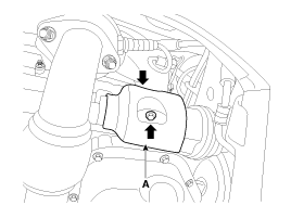
Remove driveshaft coking nut (A) from the front hub under applying
the break.
|
| 7. |
Loosen the front brake disc mount screw and then remove the front
brake disc (A).
|
| 8. |
Remove the lower arm (A) from the knuckle.
|
| 9. |
Disconnect the driveshaft (A) from the front hub assembly.
|
| 10. |
Remove the driveshaft cover (A).
|
| 11. |
Loosen the mounting bolts and then remove the inner shaft (A)
& driveshaft assembly (B).
|
| 12. |
Disconnect the driveshaft (A) from inner shaft (B).
|
| 13. |
Install in the reverse order of removal.
|
| 14. |
Check the alignment. (Refer to SSgroup 'Tires/Wheels - alingment')
|
Inspection
| 1. |
Check the driveshaft boots for damage and deterioration.
|
| 2. |
Check the driveshaft spline for wear or damage.
|
| 3. |
Check that there is no water or foreign material in the joint.
|
| 4. |
Check the spider assembly for roller rotation, wear or corrosion.
|
| 5. |
Check the groove inside the joint case for wear or corrosion.
|
| 6. |
Check the dynamic damper for damage or cracks.
|
Disassembly
|
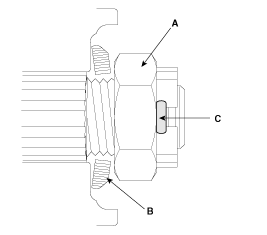
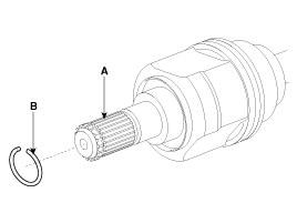
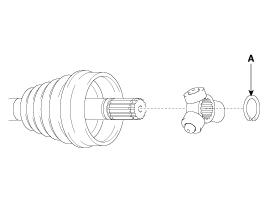
| 1. |
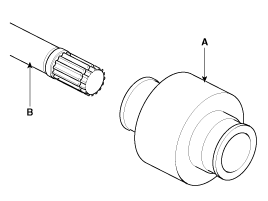
Remove the circlip (B) from the driveshaft spline (A).
|
| 2. |
Remove both boot bands from the transaxle side joint(TJ) case.
|
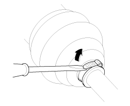
| 3. |
Pull out the boot from transaxle side joint case (B).
|
| 4. |
While dividing joint(TJ) boot (A) of the transaxle side, wipe
the grease in TJ case (B) and collect them respectively.
|
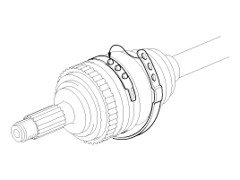
| 5. |
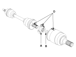
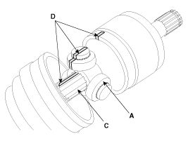
Remove the snap ring (A) and spider roller assembly from the shaft.
|
| 6. |
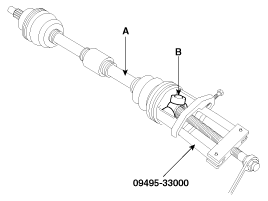
Remove the spider assembly (B) from the driveshaft (A) using the
special tool (09495-33000).
|
| 7. |
Clean the spider assembly.
|
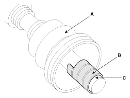
| 8. |
Remove the boot (A) of the transaxle side joint(TJ).
|
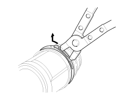
| 9. |
Using a plier or flat-tipped (-) screwdriver, remove the both
side of clamp (B) of the dynamic damper (A).
|
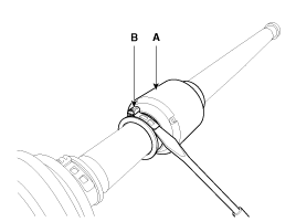
| 10. |
Fix the driveshaft (A) with a vice (B) as illustrated.
|
| 11. |
Apply soap powder on the shaft to prevent being damaged between
the shaft spline and the dynamic damper when the dynamic damper is removed.
|
| 12. |
Saperate the dynamic damper (A) from the shaft (B) carefully.
|
Reassembly
| 1. |
Wrap tape around the driveshaft spline(TJ) to prevent damage to
the boots.
|
| 2. |
Apply grease to the joint boot on the side of the wheel and install
the boot.
|
| 3. |
Install the clamp.
|
| 4. |
To install the dynamic damper (A), keep the shaft in a straight
line and assemble the dynamic damper with the bands (B).
|
| 5. |
Assemble the transaxle side joint boot and bands.
|
| 6. |
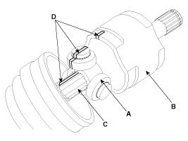
Using the alignment marks (D) made during disassembly as a guide,
install the spider assembly (A) and snap ring (B) on the driveshaft
splines (C).
|
| 7. |
Add specified grease to the joint boot as much as it was wiped
away at inspection.
|
| 8. |
Install the both boot band.
|
 Front Driveshaft. Components and Components Location
Component location
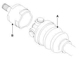
1. Driveshaft(LH)
2. Circlip
3. Transaxle
3. Circlip
4. Driveshaft(RH)
1. Driveshaft (LH)
2. Circlip
...

See also:
Seat Track Position Sensor (STPS). Components and Components Location
Components
...
Canister. Repair procedures
Removal
1.
Disconnect the canister close valve connector (A).
2.
Disconnect the ventilation tube quick-connector (B) and the vapor
tube qu ...
Tire traction
Tire traction can be reduced if you drive on worn tires, tires that are improperly
inflated or on slippery road surfaces. Tires should be replaced when tread wear
indicators appear. To reduce the ...
