 Hyundai Sonata: Mode selection
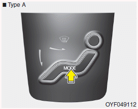
Type A
The mode selection button controls the direction of the air flow through the ventilation system.
The air flow outlet port is converted as follows:


Face-Level (B, D, E C, F)
Air flow is directed toward the upper body and face. Additionally, each outlet can be controlled to direct the air discharged from the outlet.

Bi-Level (B, D, E, C, F)
Air flow is directed towards the face and the floor.

Floor-Level (C, A, D, E)
Most of the air flow is directed to the floor, with a small amount of the air being directed to the windshield and side window defrosters.

Floor/Defrost-Level (A, C, D, E)
Most of the air flow is directed to the floor and the windshield with a small amount directed to the side window defrosters.
Defrost-Level (A, D)
Most of the air flow is directed to the windshield with a small amount of air directed to the side window defrosters.
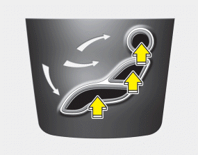
Type B
If you push the button once, the corresponding switch will turn on, and if you push the button again, the switch will turn off.
 Defrost-Level (A,
D) (Button 1)
Defrost-Level (A,
D) (Button 1)
Most of the air flow is directed to the windshield.
 Face-Level (B, C,
D, E, F) (Button 2)
Face-Level (B, C,
D, E, F) (Button 2)
Air flow is directed toward the upper body and face.
Additionally, each outlet can be controlled to direct the air discharged from the outlet.
 Floor-Level (A, C,
D, E) (Button 3)
Floor-Level (A, C,
D, E) (Button 3)
Most of the air flow is directed to the floor.
Also you may select 2~3 modes at the same time for desired air flow.
 Defrost & Face Level (Button 1
and 2)
Defrost & Face Level (Button 1
and 2)
 Defrost & Floor Level (Button
1 and 3)
Defrost & Floor Level (Button
1 and 3)
 Face & Floor Level (Button 2 and
3)
Face & Floor Level (Button 2 and
3)
 All mode (Button 1, 2 and 3)
 Heating and air conditioning
1. Start the engine.
2. Set the mode to the desired position. To improve the effectiveness of heating
and cooling :
- Heating:
- Cooling: 3. Set the temperature control to the desired position.
...
 MAX A/C-Level (B, D)
To operate the MAX A/C, turn the temperature knob to extreme left. Air flow is
directed toward the upper body and face. In this mode, the air conditioning and
the recirculated air position wil ...
See also:
Sunroof. Repair procedures
Replacement
Glass Replacement
-
Put on glove to protect your hands.
...
Description and Operation
Cruise Control
The cruise control system is engaged by the cruise "ON/OFF" main switch
located on right of steering wheel column. The system has the capability to
cruise, coast, ac ...
Rear Shock Absorber. Components and Components Location
Components
1. Self locking nut
2. Bracket assembly
3. Bumper rubber
4. Dust cover
5. Shock absorber
...
