 Hyundai Sonata: Front Stabilizer Bar. Repair procedures - Revised
Replacement
| 1. |
Remove the front wheel & tire.
|
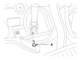
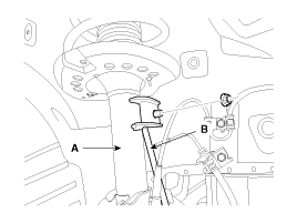
| 2. |
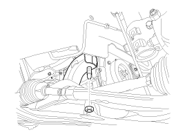
Loosen the bolt (A) and then disconnect the universal joint assembly
from the pinion of the steering gear box.
|
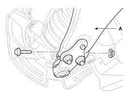
| 3. |
Remove the split pin and castle nut and then disconnect the tie-rod
end (A) from the front knuckle.
|
| 4. |
Loosen the bolt & nut and then remove the lower arm (A).
|
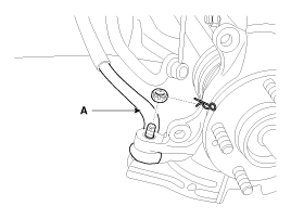
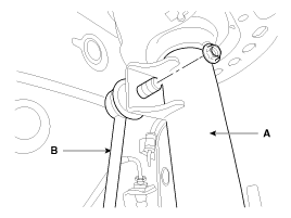
| 5. |
Disconnect the stabilizer link (B) with the front strut assembly
(A) after loosening the nut.
|
| 6. |
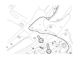
Loosen the bolt (A) & nut (B) and then remove the front roll stopper.
|
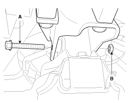
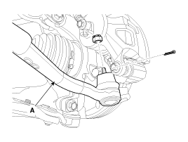
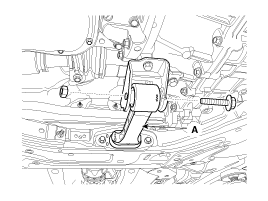
| 7. |
Loosen the rear roll stopper mounting bolts (A).
|
| 8. |
Disconnect the muffler rubber hanger (A).
|
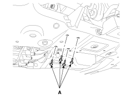
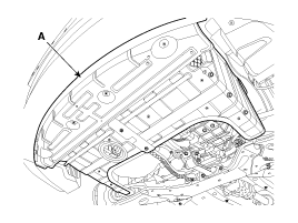
| 9. |
Loosen the bolts & nuts and then remove the sub frame.
|
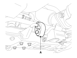
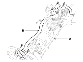
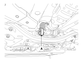
| 10. |
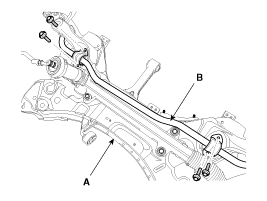
Loosen the mounting bolt and then remove the stabilizer bar (B)
from the sub frame (A).
|
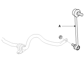
| 11. |
Loosen the nut and then remove the stabilizer link (A) from the
stabilizer bar.
|
| 12. |
Installation is the reverse of removal.
|
| 13. |
Check the alignment. (Refer to 'Tires/Wheels - alingment')
|
Replacement
| 1. |
Remove the front wheel & tire.
|
| 2. |
Loosen the bolt (A) and then disconnect the universal joint assembly
from the pinion of the steering gear box.
|
| 3. |
Remove the split pin and castle nut and then disconnect the tie-rod
end (A) from the front knuckle.
|
| 4. |
Loosen the bolt & nut and then remove the lower arm (A).
|
| 5. |
Disconnect the stabilizer link (B) with the front strut assembly
(A) after loosening the nut.
|
| 6. |
Remove the under cover (A).
|
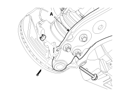
| 7. |
Loosen the bolt & nut and then remove the roll rod stopper (A).
|
| 8. |
Disconnect the muffler rubber hanger (A).
|
| 9. |
Loosen the bolts & nuts and then remove the sub frame.
|


| 10. |
Loosen the mounting bolt and then remove the stabilizer bar (B)
from the sub frame (A).
|
| 11. |
Loosen the nut and then remove the stabilizer link (A) from the
stabilizer bar.
|
| 12. |
Installation is the reverse of removal.
|
| 13. |
Check the alignment.
(Refer to 'Tires/Wheels - alingment')
|
Inspection
| 1. |
Check the bushing for wear and deterioration.
|
| 2. |
Check the front stabilizer bar for deformation.
|
| 3. |
Check the front stabilizer link ball joint for damage.
|
 Front Lower Arm. Repair procedures - Revised
Replacement
1.
Remove the front wheel & tire.
Tightening torque:
88.3 ~ 107.9 N.m (9.0 ~ 11.0 kgf.m, 65.1 ~ 79.6 lb-ft)
...
 Front Cross Member. Repair procedures - Revised
Replacement
1.
Remove the front wheel & tire.
Tightening torque:
88.3 ~ 107.9 N.m (9.0 ~ 11.0 kgf.m, 65.1 ~ 79.6 lb-ft)
...
See also:
Oil Pressure Switch. Repair procedures
Inspection
1.
Check the continuity between the terminal and the
body with an ohmmeter.
If there is no continuity, replace the oil pressure
switch.
...
ESC Control Module. Repair procedures
Removal
1.
Turn the ignition switch OFF.
2.
Remove the air cleaner assembly (A).
3.
Pull up the lock o ...
Automatic transaxle operation
The automatic transaxle has 6 forward speeds and one reverse speed. The individual
speeds are selected automatically, depending on the position of the shift lever.
To move the shift lever from th ...
