 Hyundai Sonata: Exhaust Manifold. Repair procedures
Removal and Installation
| 1. |
Remove the engine cover.
|
| 2. |
Disconnect the battery negative terminal.
|
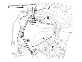
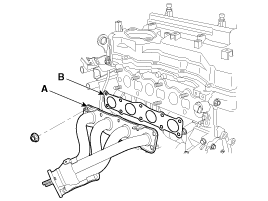
| 3. |
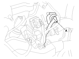
ULEV : Disconnect the front oxygen sensor connector
(A).
SULEV : Disconnect the front oxygen sensor connector
(A) and the rear oxygen sensor connector (B).
|
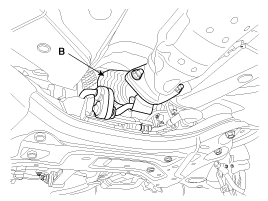
| 4. |
Remove the front muffler (A).
|
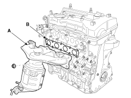
| 5. |
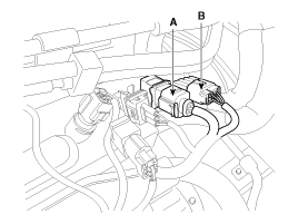
ULEV : Remove the exhaust manifold heat protector
(A).
SULEV : Using the SST (09392-2H100) (A), remove the
front oxygen sensor (B) and the remove the exhaust manifold heat protector
(C).
|
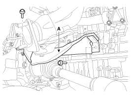
| 6. |
Remove the driveshaft heat protector (A).
|
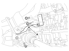
| 7. |
Remove the exhaust manifold stay (A).
[ULEV]
[SULEV]
|
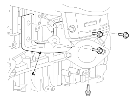
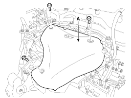
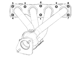
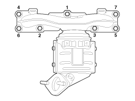
| 8. |
Remove the exhaust manifold (A) with the gasket (B).
[ULEV]
[SULEV]
When installing the intake manifold, tighten the
nuts with pre-torque first, and then tighten the nuts with specified
torque in the sequence shown.
[ULEV]
[SULEV]
|
| 9. |
Installation is reverse order of removal.
|
 Exhaust Manifold. Components and Components Location
Components
[ULEV]
1. Heat protector
2. Exhaust manifold
3. Exhaust manifold gasket
4. Exhaust manifold stay
[SULEV]
1. Heat protec ...
 Muffler. Components and Components Location
Components
1. Front muffler
2. Catalytic converter & center muffler assembly
3. Main muffler
4. Gasket
5. Hanger
...
See also:
Wheel. Repair procedures
Hub nut tightening sequence
Tighten the hub nuts as follows.
Tightening torque:
88.3 ~ 107.9 N.m (9.0 ~ 11.0 kgf.m, 65.1 ~ 79.6 lb-ft)
...
Pre-tensioner seat belt
Your vehicle is equipped with driver's and front passenger's pre-tensioner seat
belts. The purpose of the pre-tensioner is to make sure that the seat belts fit
tightly against the occupa ...
ESC OFF Switch. Description and Operation
Description
1.
The ESC OFF switch is for the user to turn off the ESC system.
2.
The ESC OFF lamp is on when ESC OFF switch is engaged.
...
