Removal
| •
|
Removal of the airbag must be performed according to the
precautions/ procedures described previously.
|
| •
|
Before disconnecting the front impact sensor connector,
disconnect the front airbag connector(s).
|
| •
|
Do not turn the ignition switch ON and do not connect
the battery cable while replacing the front impact sensor.
|
|
|
1. |
Disconnect the battery negative cable, and wait for at least three
minutes before beginning work.
|
|
2. |
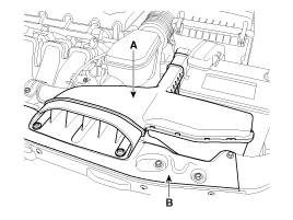
Remove the air duct (A).

|
|
3. |
Remove the radiator support upper member (B).
|
|
4. |
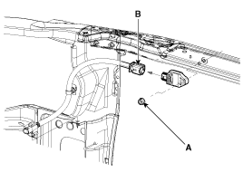
Remove the front impact sensor mounting nut (A).

|
|
5. |
Disconnect the front impact sensor connector (B).
|
|
6. |
Remove the front impact sensor.
|
Installation
| •
|
Do not turn the ignition switch ON and do not contact
the battery cable while replacing the front impact sensor.
|
|
|
1. |
Install the new front impact sensor.
|
|
2. |
Tighten the front impact sensor mounting nut.
Tightening torque :
7.8 ~ 9.8 N.m (0.8 ~ 1.0 kgf.m, 5.8 ~ 7.2 lb-ft)
|
|
|
3. |
Connect the front impact sensor connector.
|
|
4. |
Install the radiator support upper member and air duct.
|
|
5. |
Reconnect the battery negative cable.
|
|
6. |
After installing the Front Impact Sensor, confirm proper system
operation:
| A. |
Turn the ignition switch ON; the SRS indicator light should
be turned on for about six seconds and then go off.
|
|
Description
Side Impact Sensor (SIS) system consists of two P-SIS which are installed
at each center of the front door module (LH and RH) and two SIS which are installed
at each center pilla ...
 Hyundai Sonata: Front Impact Sensor (FIS). Repair procedures
 Side Impact Sensor (SIS). Description and Operation


